Test And Measurement Of RF Transformers
We’ve not posted in an age. This is the reason. Read on.
It is no great surprise that there is not a great deal of information about testing EFHW UnUns and other types of UnUn and baluns readily available.
There are reasons; it takes time and the technical requirements to make meaningful measurements and analyse them is a barrier.
We have spent months researching, reading blog posts, corresponding with knowledgable authors, watching youTube videos, testing and writing custom software. Now we feel confident.
The 4 Methods OF Measuring RF Transformers
I have used 4 methods for testing UnUns.
- Measure a link on a toroid (or other former), then from that apply a formula to calculate expected efficiencies and losses.
- Build 2 devices, connect back to back, then measure the loss through both and divide by 2 for just one device.
- Use a resistive terminator with just one device, measure and analyze for loss and other parameters.
- Bond a temperature sensor to the device inder test. Connect to a load (antenna etc), apply power then measure heat rise and from that calculate efficiency and loss.
All these tests have their limitations. But, and not to be minimized, in doing the test at least some measurement is done. In Amateur Radio – that can be unusual.
Common YouTube Videos
Pretty much universally all the YouTube videos I’ve seen show measurement done using a back-to-back method where two UnUns have their secondaries connected, then their primaries connected to VNA ports 1 and 2.
Then an S21 reading is taken and that is used for a loss measurement (by divding by 2).
There are some problems with this;
- The load presented by the secondary is highly reactive and nothing like the load an antenna makes on an UnUn so it is not a real or fair test.
- Mismatch loss and VSWR measurement of the device under test are not possible with this method. The VSWR that the device imposes directly affects loss and can be a significant indicator of a poor design.
The only advantages are that it is simple and it provides a number than can be used for comparison.
A Better Test Method
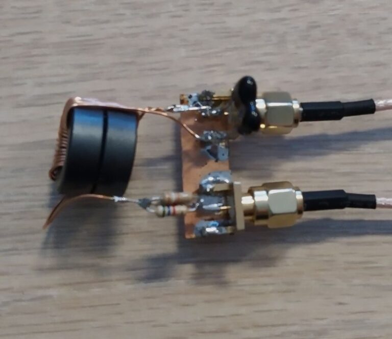
People with vast experience in RF Engineering use a load resistor and a singe device (UnUn / balun / transformer) to perform test and measurement analyses.
The load resistor forms a voltage divider on the output of the UnUn (device under test) that in combination with the VNA port impedance present the correct impedance for the UnUn (device under test).
There are some issues with this – which I have found and with assistance found solutions for.
One large hurdle is the time required for analysis of the measurement results. Getting values, plugging them into a (clever) calculator etc takes time.
Example
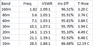
Not bad! This shows the VSWR change over frequency which points to where loss is increasing. The expected temp rise – also interesting, indicates likely core heating under power.
Test Results
The spreadsheet to the left is generated from our custom software. Just feed it an ‘.s2p’ sweep file from your nanoVNA, and a calibration file for any load resistor – press the button then done.
A full explanation of how this is done, and what the results really mean will be in a subsequent post.
Note also – the distribution of loss between mismatch, core, and total is not shown. More on that to come.
In A Subsequent Post
I shall outline, then detail how single device and resistive load measurements are done, and the results as presented above can be generated.