Modelling And testing At OZ-Tenna
In the last week Amateur Radio activities have had to take a back seat to work and family life, but some maybe interesting things have happened.
Common Mode Current Measurement
Ages ago I made a clip-on ferrite based sensor, added a diode and some caps and a burden resistor to make a common mode current meter. Just clip it over a coax and measure with a multi-meter to get current.
Well it is not really suitable for measuring current in radials. It needs its own moving coil meter. So I bought a 50uA movement and am in the process of rebuilding it into something more practical for field measurements.
I designed and printed a bezel to take the meter and a range switch – 0.5W or 5W ranges. Since I run QRP, testing with low power means a 0.5W range makes sense.
Oh. I’m using 20 turns on the clip on ferrite. The reason, instead of using 10, is to increase the voltage so that diode conduction at low power is make more linear. Remember, even a germanium diode needs around 0.2V for conduction.
Here is an article by W8JI on this. It is a good read.
Antenna Modelling – The EFHW
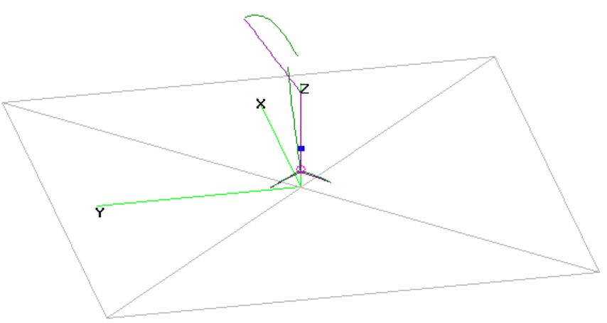
See the image at the top of this post.
It is an EFHW cur for 40m installed as an inverted-L with 2 short 2m long radials. You have to look closely to see the green current lines on the radials.
I’ve been using 2 radials, each 0.05 wavelengths long on my 40m/20m EFHW antennas for the last 9 months or so. As per common Ham folk lore “it works great” but using 2 radials versus 1 is totally untested or modeled or measured.
So I modeled it. Well, to cut to the chase; one radial works just as well as 2. Yes, the current is divided on 2 radials. Yes both radiate. Yes both work, but 1 radial looks like it will work well.
So that is why I’m getting the common mode current meter working and more practical. I can test with 1 and 2 radials, and test what is happening on the coax also.
Here is the mantra “If I haven’t measured it, I don’t really know.“
Antenna Modelling – The Dodgy OCF Model
A friend was send an EZNec model that was intended to show that his antenna was not doing what it should and had a huge common mode current issue.
He is feeding it with TV ribbon. This was heresy to the person he was corresponding with.
Well, I loaded the model into 4Nec2 and indeed, the common mode current in a feeder was high. That surprised me. Then I ran some far field calculations with a 10m feeder on it and the gain looked kind of ok, or maybe a little high at 10dBi. Then I changed the feed line length to 5 meters long and the gain went to 20dBi. Whacko! This was a huge red flag. No way was a wire antenna going to give that.
On investigation I found that the feeder was shorted together at the far end hence the common mode current on it was high. Then the 2 arms of the OCF were shorted at the same point. So basically it was a flat top with a shorted feeder.
The end result – I fixed the model and the gain came down to realistic levels. AND the common mode current went back to something more realistic.
It was amusing – someone claiming something based on a rubbish model, clearly not doing the testing that should have been done. My friend said the original modeller was very good with antennas and RF etc. Clearly he didn’t pay attention to the model he used in his argument.