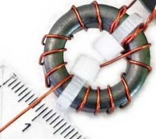
I saw one of these last week on the internet. It is a beautifully packaged FT82-43 UnUn that has a 2 turn primary and 14 turn secondary, the turns are spread out and has the magical bifilar primary. It was well made and looked pretty good.
There is one problem. It is very inefficient. It will probably have a great SWR just like a dummy load.
Owen Duffy in his remarkable blog gave a simple test I followed.
Put a 2 turn link on an FT82-43 toroid. Then use a nanoVNA to measure “Rp” – then calculate the efficiency using Efff% = 100 * 1-50/Rp
Then you find at 3.5mHz it is 31% for this simple design. On 10m it is around 60%.
So your 10 watt signal becomes 3 watts on 80m. How can that be good?
The rise in efficiency with increasing frequency of this magnitude is hinting that the 2 turn winding is insufficient on the lower bands.
Change to a 3 turn winding. You get 68% on 3.5mHz and 80% on 10m.
So now you have doubled the amount of power hitting the antenna for the cost of one extra turn on the primary and a few extra on the secondary. That sounds like a bargain to me.
So for the cost of one extra turn on the primary and a few extra turns on the secondary, you get half the loss. You will also get less heating – as that is where all the loss goes.
Do You Want Even Less Loss?
If like me the answer is yes, then the solution is pretty darned elementary.
Stack 2 cores. Super glue them together into a neat stack.
Use a 3 turn primary.
Your losses will be halved again – or 1/4 the loss of a 2 turn primary on a single core.
My tests show for 3 turn primary on 2 cores stacked and using the nano VNA and Rp link test, you should get around 84% efficiency on 80m and 90% efficiency on 10m. The characteristic impedance test shows less loss, and a real life heat rise test shows less loss again.
Your Transceiver And Efficiency
What is happening? Why do the turns matter?
Your transceiver needs to work into a load, this is the primary of the transformer or UnUn – that suits the transceiver. Sure, the secondary and what is connected to it matter a lot, but if you want optimum results, you need a basic minimum impedance to operate into.
The better you match the transceiver to the antenna (no big surprise – sorry), the better the efficiency.
This “match” is super-highly dependent on the type of core material, its size and its shape. And the number of turns.
Geometry matters.
This might seem odd but it is a major factor in efficiency.
Cores shaped “like a bicycle wheel” with a comparatively large hole and a thin and shallow rim are not very efficient.
By stacking 2 cores you change the geometry, you make it taller, and this has a large effect.
The FT82-43 is not a very good shape. Its rim is quite shallow and thin which is why stacking 2 of them makes such a big difference.
The turns on the primary are critical also.
For the 2 turn primary on the FT82-43, it is just not a good enough load for the transceiver, power is wasted. As you add more turns, the match to the transceiver improves. Yes – this is a terrible dumbed down description – but that is the effect.
Note. If you add too many turns you go past that ‘sweet spot’ and the match to the transceiver gets worse again and efficiency drops off.
Now, when you stack 2 cores, your 2 or 3 turn primary changes the way it matches to the transceiver, dramatically. You are giving the transceiver a vastly different load. It just so happens this has not gone past that sweet spot, yet.
There is also another effect. As you go up in frequency you’ll find that on 10m, for example, the efficiency drops as on those frequencies you’ve gone past the ‘sweet spot.’
But wait – there’s more.
The above will probably not apply to other cores. For example the FT140-43 will behave differently – it may be too much to have 3 turns on it. The FT240-43 – same, it will be different again.
Monkey See - Monkey Do
The FT82-43 “design” with a 2 turn primary and 14 turn secondary is a direct translation from the FT240-43 version with the same windings.
The fact is these 2 ferrite cores are very different. Another fact is that the FT240-43 version is not very efficient either.
This is a classic case of a design that is not very good being copied and then used inappropriately.
As above – just adding an extra turn halves the loss and stacking 2 cores halves it again.
For even the most space and weight sensitive application, having 2 cores will not present an onerous increase in weight.
How You Wind The Turns Matters Also
Can someone please explain why the torid is wound as per the picture above? The 2 turn primary is bifilar wound with the secondary, and the secondary is spaced out to fill the core.
Why? What magic does this impart?
Owen Duffy in his excellent blog points out this type of winding only contributes loss to the design – and it has no practical merit.
From a transformer basics point of view, dumbed down, the idea is to link the flux in the primary with all of the turns in the secondary to be able to transfer power. The toroid by its nature will help with this, but deliberately making it hard just does not help.
Owen in the builds he has done uses an autotransformer winding which is just a number of turns with a tapping. For 49:1 it is 21 turns tapped at 3 turns. This is a 7:1 turns ratio hence 49:1 impedance ratio. He winds them all togther, no gaps, and gets the best possible efficiency.